
Infrastructure
General description of test facility
It is well known that Greece suffers from destructive earthquakes. Obviously, the best way to mitigate the effects of earthquakes is to improve knowledge on the structural behaviour and to compile the necessary regulations for earthquake design.
Ever since 1965 a mechanical shaking table was used for earthquake related research at the Institute for Structural Analysis and Aseismic Research of the National Technical University of Athens (NTUA). Research was done there especially on scaled models in conjunction with a series of analogue computers. Later on, based on this experience, Professor P. Carydis, the first director of the Laboratory for Earthquake Engineering (LEE) of the NTUA, co-innovated with the American company MTS what in 1981 was a new kind of shaking table.
The destructive earthquakes that occurred in major cities of Greece during the period 1978-1981 resulted in an initiative for the construction of the shaking simulator at the LEE of the NTUA. The entire project was funded from national sources. The simulator consists of a rigid platform 4mx4m, with 6 degrees of freedom and of a system controlling the input motion and monitoring the response of the specimen tested on the platform
The earthquake simulator was calibrated and became fully operational at the beginning of 1986.
The 6 DOF shaking simulator with its control system was, at that time, unique. It was manufactured in the USA with the exception of the steel table as well as some minor items of the facility that were constructed in Athens. The weight of the reinforced concrete reaction mass amounts to 25MN. The facility has a full active control along the 6 degrees of freedom. The whole laboratory and the adjacent to it office building was specially designed and constructed to serve the facility under consideration.
The main characteristics of the earthquake simulator may be summarised as follows:
Platform
. Dimensions: 4x4x0.6 (m3); Weight: 100(kN); Material: Steel
. Number of independent degrees of freedom: six(6)
. Max Weight of Specimen: 100(kN), if center of mass is at 2(m) above the Simulator's platform.
. Max Horizontal Force (at each direction X,Y): 320 (kN)
. Max Vertical Force (direction Z): 640(kN)
. Max displacement of the platform (each axis): ± 10 (cm)
. Max rotation (about each axis) ± 7x10⁻² (rad)
. Max acceleration to each horizontal direction (X, Y): 2.0 (g)
. Max acceleration to vertical direction (Z): 4.0 (g)
. Max Velocity to each axis (simultaneous performance): 100 (cm. sec-1)
. Operating frequencies (for each degree of freedom): 0.1-50 Hz
. Electric Power Installed: 1200 kVA
Control
Analogue Unit: Specific analogue unit with which the user has the possibility of independent performance of each degree of freedom. The unit can produce and combine: sinusoidal, quadrangular etc vibrations for each direction simultaneously. External recordings of other receivers can be used to provide input to the analogue unit.
Digital Unit: PC based digital unit. Possibility of exciting the platform with strong motion data stored in the computer, through D/A converters. The six degrees of freedom can be excited simultaneously or independently. Creation of input signals with specified spectra or other characteristics. In parallel, to main pc a second control unit is functioning based on PC. With this acquisition, it is possible to handle longer input motions (of several minutes duration) to increase the resolution and to accelerate the evaluation of results.
Table Motion Control Software
The main functions provided by the software are the following:
1: Waveform creations;
2: Real-time test control,
3: Control enhancement iteration,
4: Table motion analysis,
5: Library handling and
6: Graphic display.
1. Waveform creation
Several types of waveforms can be created and stored in a special profile library. These profiles can then be allocated as desired to the various motion control axes on the table for a test. The following type of waveforms can be created: sinusoidal, sine sweep, random, random based on a response spectrum definition, and tabulated entry of field recorded earthquakes. The response spectra software utilises a special technique, which allows long random time histories to be created and iterates on the random waveform more exactly to the response spectra definition. It is generally believed that this results in a higher-quality test.
2. Test Control
The software supports flexible selection and scaling of profiles for usage in single or multiple degree-of-freedom seismic testing. For example, six profiles could be selected and assigned to each axis for a full six degree-of-freedom test. The actual real-time control software synchronises the starting and stopping of the test, and control, the D/A and A/D hardware. Several steps are taken to safely initiate and terminate the test process.
3. Control Enhancement Iteration
There are available special software procedures for compensating the drive way waveforms to obtain greater response accuracy and fidelity. The technique involves determining a transfer function for the system and then modifying the drive signal to account for the effect of the transfer function. The functions provided are: transfer function determination, auto and cross-spectral density function determination, coherence function determination, and compensated drive determination. The transfer function models are stored in a special library and can be applied to different tests as required.
4. Table Motion Analysis.
Several table motion parameters are usually recorded for each test. These parameters can be displayed immediately and special calculations are performed to verify proper table performance. These can be compared to similar calculations performed on the desired table motion waveforms. Functions included: response spectra, acceleration, Fourier amplitude and total earthquake energy calculations.
5. Library Handling Utilities
Several libraries discussed above, are used to organise information related to the seismic testing process. Special software functions are available to maintain this information and they include listing, deletion, and copying commands. The copy command allow test data to be transferred to archival tape or disk, and can access properly formatted profiles created independent of the seismic software.
6. Graphic Display
Throughout the seismic testing process, provision is made to allow easy graphical display of time history and special information of flexible formats.
Data Acquisition System: Specific Unit with 64 channels Analogue/Digital with high sweeping frequency, for the attendance of dynamic phenomena from several receivers (Strain gauges, accelerometers, etc).
Storage of recorded signals (hard disks, floppy disks, CD's, tapes): Evaluation of input signals or specimen response records with the software libraries of the computer of the Laboratory for Earthquake Engineering. The raw data can be immediately evaluated and printed out or can be stored in any modern means of electronic storage, through special devices (CD writers, disk writers, tape writers). The control unit has been connected through optical fibres to the visitor's rooms for further data evaluation and reduction.
Data Analysis Software
When large-channel data acquisition is resident on the seismic computer system, a companion data analysis package is available to streamline the examination and reduction of the specimen data. The functions to be developed have not been finalised, but a preliminary list is presented. The software functions fall into three categories: a. configuration; b. the series analysis; c. spectrum analysis.
a. Configuration.
The software provides the ability to configure the data acquisition channels with special names to identify the actual transducers located at the specimen. In this way, the data for single-output transducers such at LVDT's accelerometers, and multiple-output transducers such as rosette gauges can be analysed by using logical and meaningful names. This feature reduces the possibility of error when manipulating large amounts of data.
b. Time Series Analysis
Several functions are available to operate upon data in the time domain. Some of the functions result in new time histories and others determine key characteristics. They are listed below: Decimation, arithmetic manipulation, digital filtering, differentiation, integration, mean level, extreme value, rms acceleration, total earthquake energy, strain gauge reduction.
c. Spectrum Analysis.
Several functions are available which operate upon data in the time domain and result in various types of frequency spectrums. They are listed below: Forward and inverse Fourier transformation, response spectrum, auto-spectral density, cross-spectral density, ordinary coherence, transfer function.
Reaction wall
An independent reaction wall facility is functioning at the backside of the laboratory. Its capacity is 10 MNm, 6m height and two pieces: 4 and 5 m long, 1.1 m width, out of steel. Several jacks may function with independent control, with a new oil pump. The jacks have capacities of 500 kN, 300 kN, 200kN and 100kN. A mobile data acquisition system of 16 channels is supporting this facility.
Shear Walls Testing Apparatus
An innovative testing apparatus is functioning in the laboratory in order to test under recyclic loads horizontally applied, small walls of any dimension ( up to 2 m height, 1.5 m long, 1.0 m thickness). The vertical load may be up to 1000 kN and can be kept constant without any variation through out the tests.
Elastomeric Isolators Testing Apparatus
An innovative testing apparatus for elastomeric isolators is functioning in the laboratory. A strong beam with only vertically sliding supports is bridging the shaking table. The horizontal motion of the 'bridge' is restricted. The elastomers are put between the 'bridge' and the surface of the shaking table and may be tested under the full capacity of the shaking table mentioned above.
FRP Testing
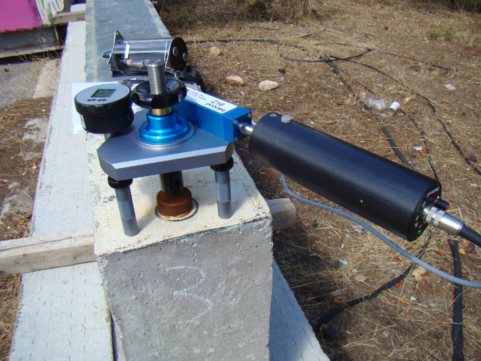 |
Quality Control Pull-off Testing for FRP Installation |
Pull-off Tester |
In-situ Masonry Testing
 |
Measurement of Loading and Mechanical Properties on Masonry |
Flat-Jack instrumentetion |


